MagSW v10a
Magnetic switch for remote-controlled models
November 12, 2018
18-NOV-2018: Added pictures to the gallery and updated the e-mail link (web@panacek.net) in the footer.
The Story
It has been already several months since Pad (Pavel D.) asked for a simple and cheap magnetic switch for his ACES aircombat planes. A magnetic switch replaces the traditional mechanical switch, which is often a source of reliability issues. There are already several commercial products or even some DIY solutions available. However, they are either hard-to-get or rather expensive for what it is.
I was just about to restart my hobby, Pavel knew exactly what he wants and I do electronics for a living. It sounded like a fun project and for this reason, I decided on designing and building my own magnetic switch. The design puts emphasis on the cost, size, weight, reliability and being open-source. All considerations follow the KISS (keep it simple and stupid) principle. This article describes the result.


Technical Data
| Parameter | Value |
|---|---|
| Operating voltage range | 3-18V |
| Maximum continuous current | 4.43A |
| Typical on-resistance | typ. 34mΩ |
| Standby current | <4uA |
| Operating temperature | -40 to 80°C |
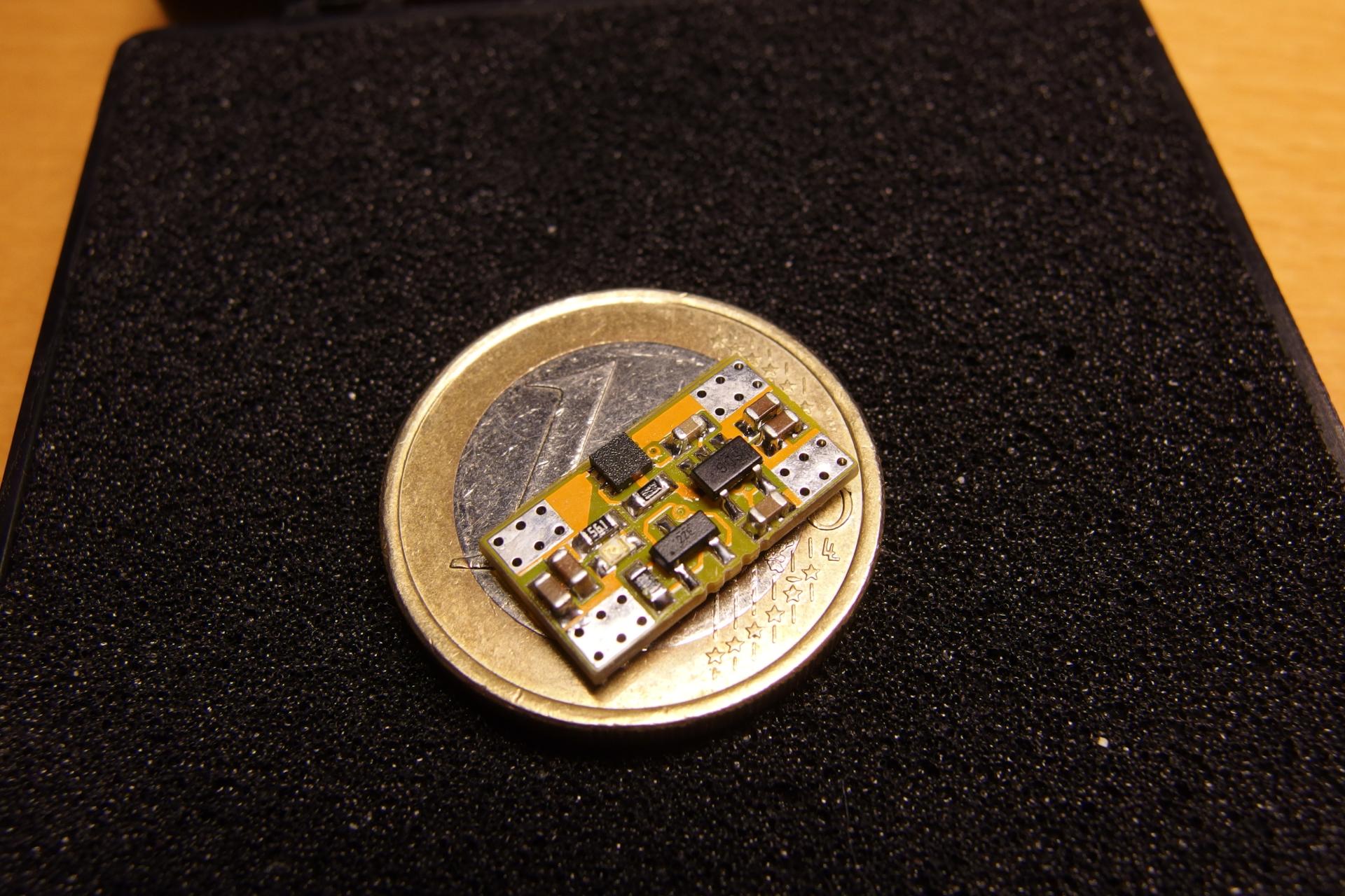
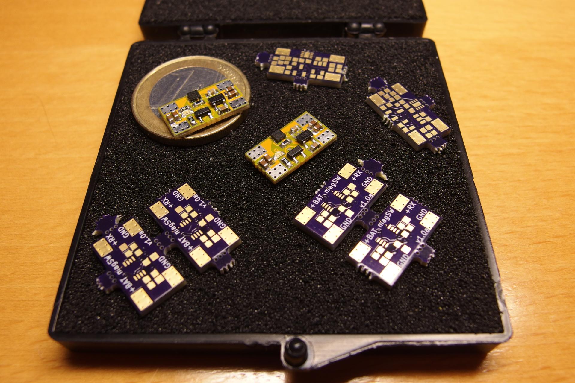
| Dimensions | 15x8mm (bare PCB) |
| Weight | 0.48g (bare PCB) |
| Protections | overcurrent, overtemperature, starts always-on |
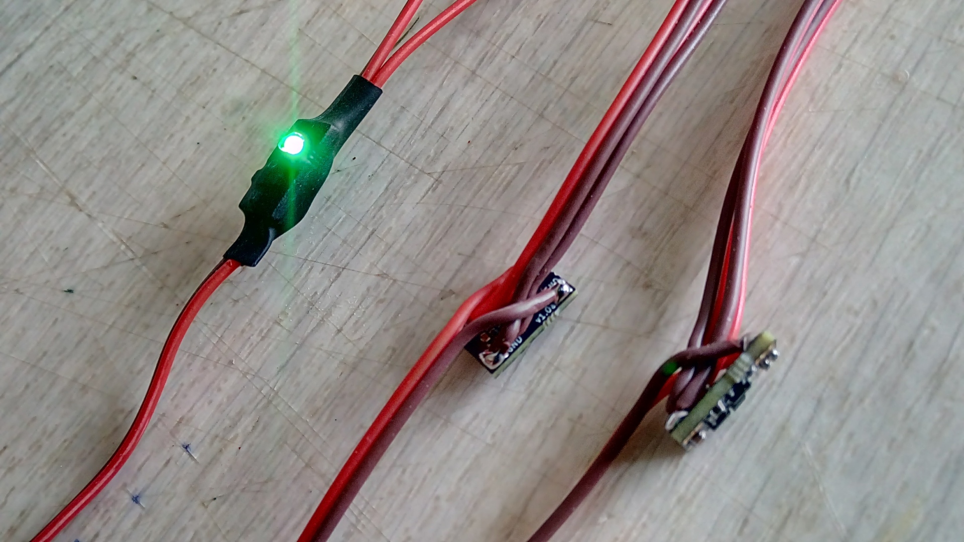
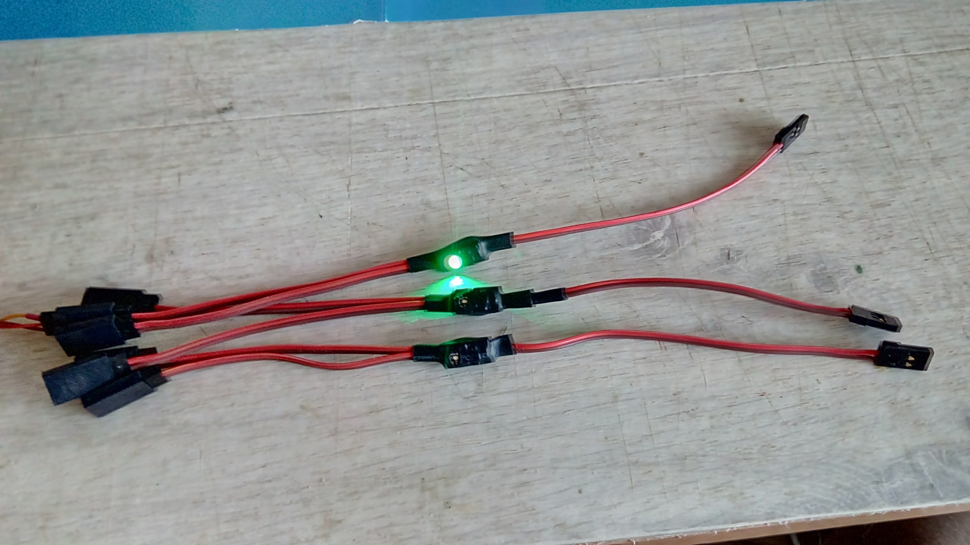
| Status indicator | 1x LED, lits when on |
| Required magnetic field | >63mT |
| Memory | typ. 5s (the off state only) |
Description
An electronic circuit which replaces the functionality of a traditional mechanical switch must solve several challenges. First, the circuit should ideally drive zero standby current when the switch is off. This is not possible because the switch memory and the hall sensor operate all the time. Second, the switch memory shall acknowledge only the valid command from the operator. This is a problem in case of a hall-based (magnetic) switch which may pick-up noise and stray magnetic field from the system, especially in electric-powered models with high currents. Aside of beforehand mentioned, the circuit startup behavior shall act in the way that the switch always turns on after connecting the battery. This significantly improves the reliability of the system. It is unlikely but possible that the switch and the battery temporarily disconnect during the operation. It can happen due to mechanical stress, vibrations or a worn connector. The “start-always-on” behavior increases the chance of landing the precious R/C model safely. Otherwise, the switch may remain off, dooming the R/C model for no obvious reason.
Although the description is not complicated, the circuit implementation is rather tricky. Simply put, requirements for low standby current, glitch-free command, start-always-on together with the small size and low-cost design are difficult. It is not surprising that most commercially sold magnetic switches for R/C models use a small microcontroller (MCU) such as PIC, MSP430 or ATTiny. A microcontroller in the system elegantly solves all problems described in the previous paragraph. However, the MCU requires programming and also flashing the binary code for every single unit built. Not to mention proper testing. It is simply not as easy as it sounds.
MagSW v1a uses a different approach with two key differentiators from the known solutions:
- it does not use any microcontroller,
- it uses a highly-integrated high-side switch instead of a simple MOSFET for the switch.
The first reason why it can get around without a microcontroller is the DRV5032ZE hall sensor from TI. The sensor exists in a few versions with different sensitivity. MagSW uses the least sensitive -ZE version with the threshold of 63mT. This is a relatively high threshold which helps to suppress stray magnetic fields. For example, a current of 300A through a conductor generates a magnetic field of 60mT in the distance of 1cm from the conductor. Additionally, the sensor draws only 1.6uA. The second reason is the 74AUP1G74 flip-flop. It is a D-type flip-flop with clear and preset inputs which allow for setting the default “start-always-on” behavior. The logic gate draws as low as 0.9uA of standby current. An ultra-low iq linear regulator TPS70933 powers both, the sensor and the flip-flop. The regulator has a reverse current protection feature. This feature prevents the flow of current from the output to the input when the output voltage is higher than the input voltage. This means that the logic circuitry can temporarily live from the output capacitor which implements a memory.
MagSW implements TPS259571 high-side switch (eFuse) instead of a traditional MOSFET. The integrated high-side switch acts as a normal switch but comes with a complete set of protection features. Most importantly, it is able to detect overload and overtemperature event with auto-retry behavior.
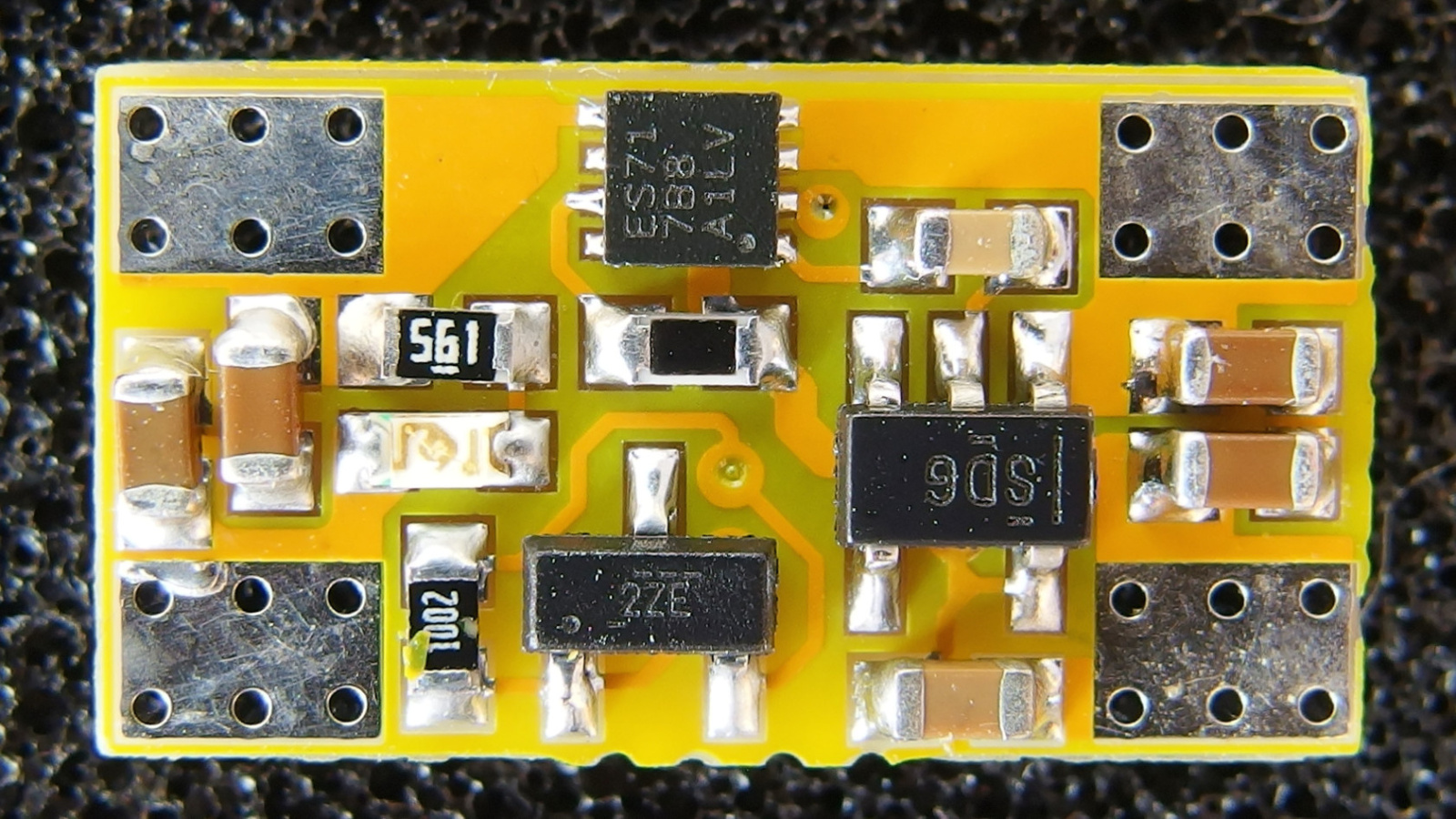
The Circuit
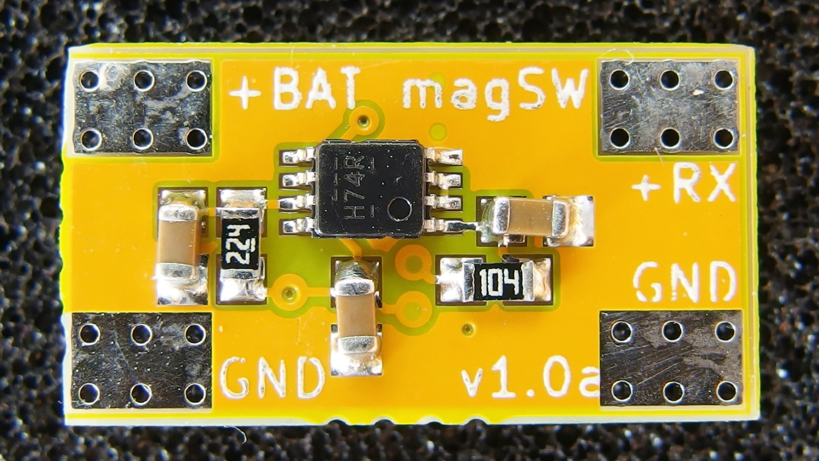
Positive terminal from the battery connects to the pad J1 (+BAT). Positive terminal from the load (receiver) connects to the pad J3 (+RX). Pads J2 and J4 are common ground (GND). Input and output capacitors C2, C3 and C7, C8 are connected in series. This prevents catastrophic failure if one of the MLCC capacitors cracks and shorts. This is a design practice from the automotive industry. Capacitor C4 sets output slew-rate and resistor R3 sets the current limit threshold for the high-side switch U3. The LED D1 indicates the ON state. The resistor R5 limits the current through the LED. The linear regulator U1 with the required output capacitor C1 provide stable 3.3V for the logic. The hall sensor U2 has an open collector type of the output. For this reason, it requires a pull-up resistor R1. The RC low-pass filter R2, C5 removes possible noise which could trigger the D-type flip-flop U4. The resistor R4 and capacitor C6 define the startup behavior. The time constant is set in the way that the !PRE pin latches logic zero longer than it takes DRV5032 to set the output to logic one after the startup. Capacitor C9 is a bypass capacitor.

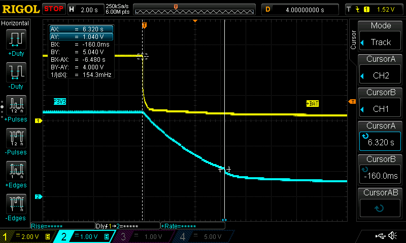
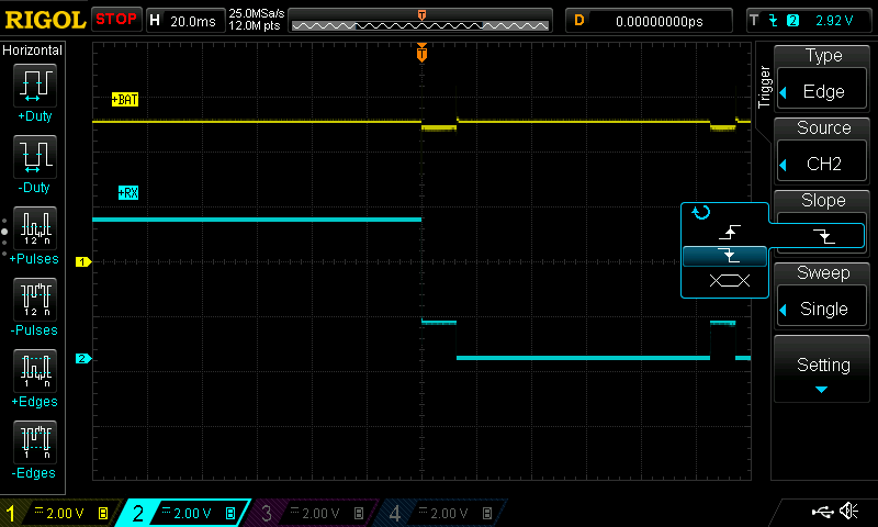
Just a few words about the switch memory and the start-always-on feature. It is important to understand that the functionality of both features partly overlaps. When you disconnect the battery, the flip-flop operates from the charge stored in the capacitor C1 and input capacitors C2, C3. Design parameters guarantee that the switch remembers the state for the supply voltage down to 2V. This is the minimal (guaranteed) voltage for the logic-high level on the CLK and PRE pin for the nominal 3.3V supply. For this reason, the flip-flop does not recognize any change after reconnecting the battery. In the case the voltage on the P3V3 rail drops further, the flip-flop relies on a different slew-rate of the PRE and CLK signals. This implements the “start-always-on” feature. It is a gray, hard-to-debug zone but extensive testing shows expected behavior. Also, note that the load depletes the charge stored in input capacitors quickly if the disconnect occurs during the ON state. Additionally, the switch remembers the OFF state typically more than 5 seconds. That’s having said, the switch turns always ON unless it remembers the OFF state. The table below explains the behavior.
| Previous switch state | New state (delay < 5s) | New state (delay >5s) |
|---|---|---|
| OFF | OFF | ON |
| ON | ON | ON |
Measurements

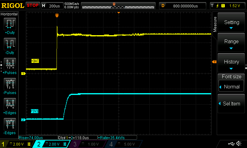
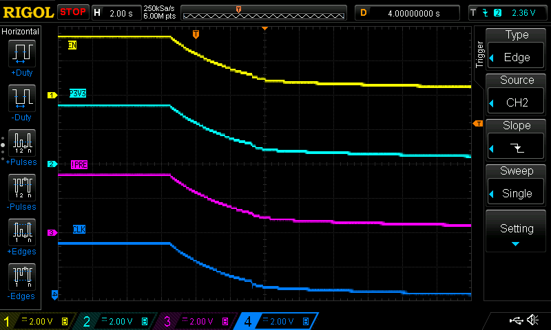
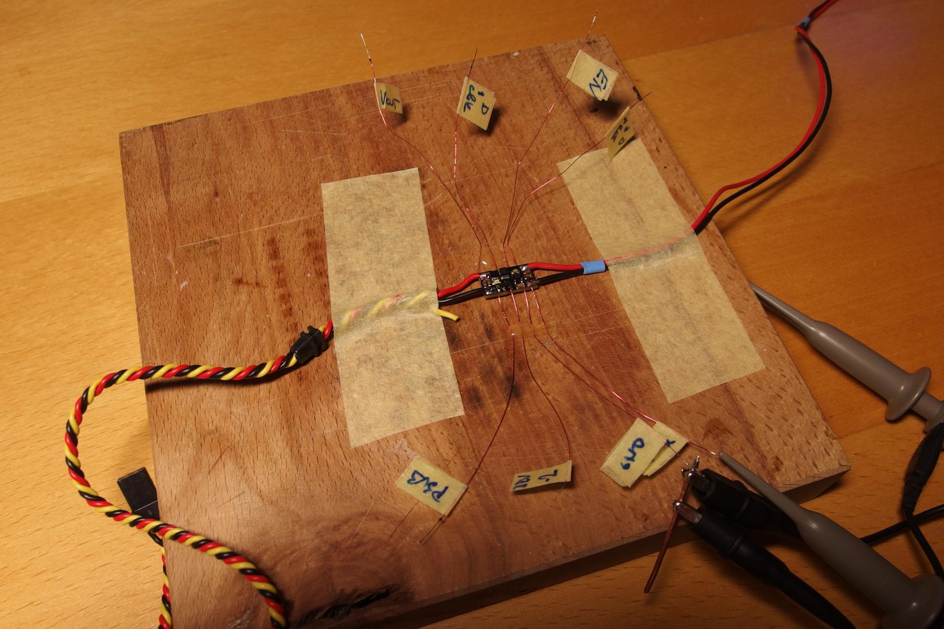
The turn-on behavior. The circuit supplies a receiver with two servos from the lab power supply. The noise on the yellow trace is due to the mechanical insertion of the banana plug. Note the output voltage slew-rate set by C4.
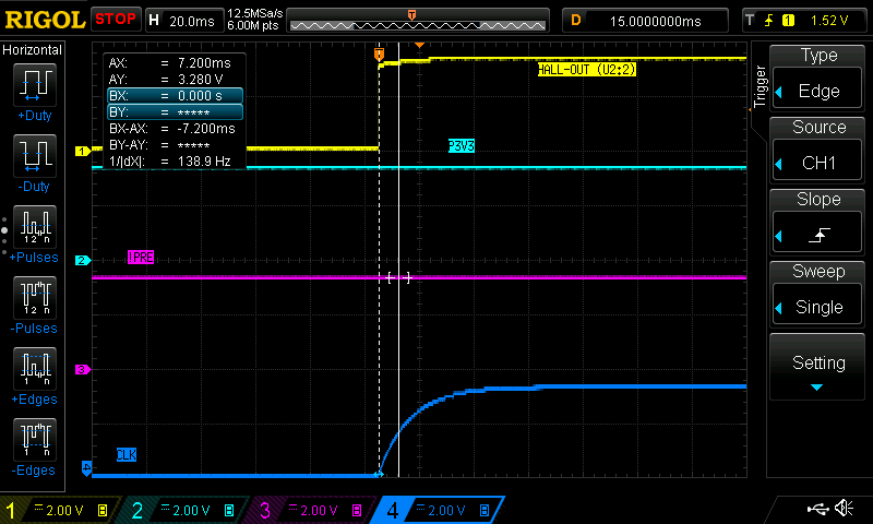
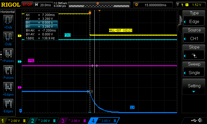
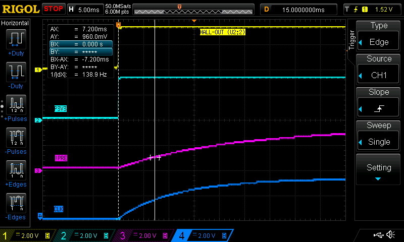
The turn-on behavior of the logic circuit during the cold start. Note the different slew-rate for the PRE and CLK signal.

Using the MagSW v10a
Using the switch is very simple and does not require any configuration. Connect the positive battery terminal to the +BAT pad and the negative battery terminal to the GND pad. Likewise, connect the positive terminal from the load to the +RX pad and the negative terminal to the GND pad. Make sure you’re using a strong magnet. A neodymium magnet from an old BLDC outrunner is a good candidate. Holding on the magnet in close proximity to the hall sensor toggles the switch. Note that the flip-flop reacts only to the transition. For this reason, you need to hold the magnet long enough to overcome the de-glitch period and then move the magnet away from the hall sensor to register the change. The video below is worth a thousand words.
Building Your Own Copy
The circuit itself is simple with only a few components. However, I don’t recommend building the MagSW v10a unless you have experience with soldering SMD components. Using bigger passive components would be possible but the integrated circuits come only in tiny SMD packages. Especially the TPS259571 is in an extremely small QFN package which makes it impossible to solder without a hot-air soldering station. On the other hand, it is not rocket science and a basic hot-air station from China starts from 35 USD. I use 858D and it works reasonably well. Additionally, stick with components from reputable brands (Vishay, TDK, Murata, Yageo, Taiyo Yuden, Samsung, AVX etc.) and source them from verified suppliers like DigiKey, Farnell or Mouser. Direct sourcing from China is definitely a wrong idea because you never know what you get. I suggest 1% tolerance resistors and X7R or X5R capacitors with adequate voltage rating. The bill of material below lists components I used. You can order the PCB from OSH park for extremely low price and free shipping all around the world. Just click here.
Design Data
MagSW v10a Complete KiCad 5.0.1 Project
MagSW v10a Schematic - PDF
MagSW v10a Gerbers
MagSW v10a BOM - MS Excel
MagSW v10a Interactive BOM
Conclusion
I’ve already built about 50 modules (October 2018) and have not heard any negative feedback yet. Practically all of them are in use in ACES aircombat R/C models with three to four servos. Extremely small size of the module makes it great fit also for the F3K category. It is also possible to pot the switch with a hot-glue gun and make it water-resistant. This would probably work nicely for boats.
FAQ
Q: Do I need to disconnect the battery after flying?
A: No, the switch draws extremely small standby current and disconnecting the battery is not necessary. The switch consumes approx. 0.7mAh/week.
Q: Can I charge the battery through the switch?
A: No, the high-side controller does not support bidirectional current flow.
Q: Can I build and sell this circuit?
A: Yes, you can build as many copies as you want and use it for your own profit. Read the license first.
Q: Does the switch implement reverse polarity protection?
A: No, reverse polarity event will most likely permanently damage the device.
Q: I accidentally reversed polarity and now my switch does not work. What can I do?
A: Typically, one of the ICs blows up. Check if there is 3.3V on the output of U1. If not, replace U1. Alternatively, change the high-side switch U3.
Q: What happens if I overload the switch or short the output?
A: The switch is durable against overload or even short. When the switch detects current above the 4.43A limit, it switches off. Additionally, the auto-retry feature periodically checks if the short is still present. Refer to the datasheet of TPS259571 for the detailed description.
Credits
Special credit goes out to Bud Bennett. His designs were a good source of inspiration. Check out his magnetic switches on hackaday.
License
All design data are licensed under CERN Open Hardware License v.1.2 or later. If you like the design, please consider buying me a beer (PayPal).


